
Other details about the equipment are shown in Figure 13-11. When a pipe is connected to a piece of equipment, nozzles are shown double line.
PIPING ISOMETRIC PROGRAM SOFTWARE
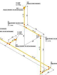
However, it is not unusual for some companies and some CAD software packages to draw elbow symbols with round corners. Isometric drawing symbols for 90° and 45° elbows are typically shown with square corners, as opposed to the round corners found on arrangement drawings. When the pipe aligns with the centerline of E-101, another elbow turns the line up and into nozzle C. Notice the elbow is also shown turning west on the iso. Also, recall elevation changes can be shown on the piping arrangement drawing in the form of callouts, but the elevation callouts must be adequate enough to determine the length of the pipe traveling in the vertical plane.Īfter the north run, an elbow turns west and line 01-2-C30-10" travels below vessel E-101. Remember, horizontal dimensions are calculated using coordinates and vertical dimensions are calculated using elevations. If there were a need to determine the distance a pipe travels in a vertical plane, a drafter would need one of the following: elevation callouts (found on the plan view drawing) or an elevation drawing that graphically depicts the amount of vertical change. To determine the distance a pipe travels in the north direction, or any other horizontal plane, one must establish the length using two coordinates. If line 01-2-C30-10" turns north on the arrangement drawing, it must also be shown turning north on the iso. ASTM A182 Pipe Olet ASTM A53 Steel Pipe ASTM A106 Steel Pipe ASTM B88 Copper Pipe If you have any suggestions about added standards, please let us know and we will look into adding them. The elbow is oriented toward the north according to the north arrow. The line begins at nozzle N1 with a flange and elbow welded together, fitting make-up. Use the procedure that follows to render a piping isometric for line 01-2-C30-10".Īs shown in Figure 13-11, line 01-2-C30-10" is attached to vessel V-101 at nozzle N1 and nozzle C of vessel E-101. Piping isometrics are generally drawn to represent the configuration up to and including the first fitting in the piperack. However, this does not apply to a pipe in a pipe-rack. Remember, the isometric must provide a detailed description of the pipe's routing from beginning to end. By using this information and the isometric symbols that correspond to the various orthographic drawing symbols the pipe drafter can render an isometric describing the pipe's routing. Drawing symbols, callouts, coordinates, and elevations provide detailed information of the pipe's configuration and routing through the unit.

As an isometric for a particular line is developed, constant reference to the piping arrangement, section, or elevation drawings is essential.


 0 kommentar(er)
